
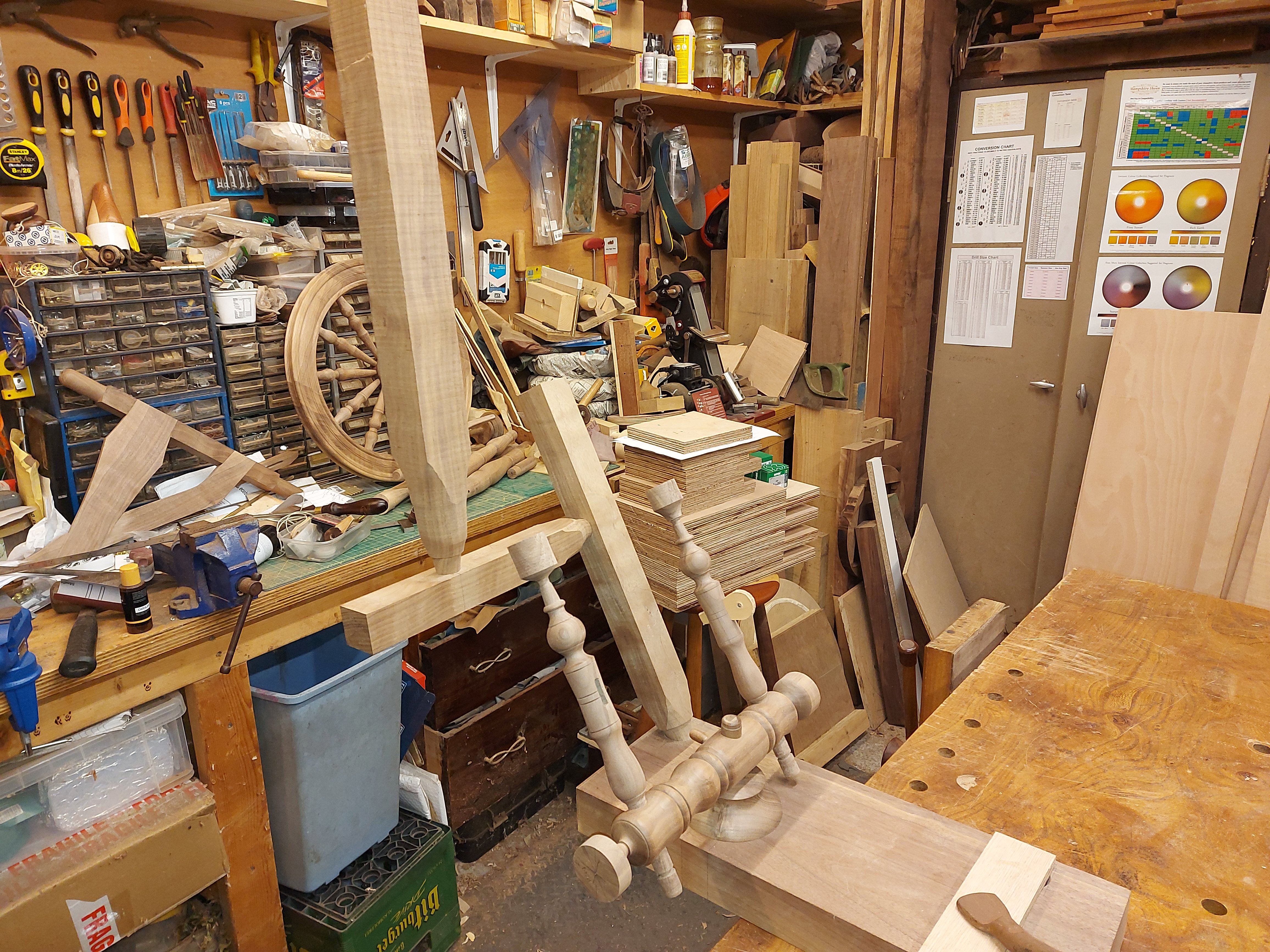
Earlier this year, for no reason that I can discern, I decided that I wanted to build a spinning wheel. I had no particular interest in spinning, nor any need for a wheel. The best explanation I can come up with is that I am drawn to the past, and the old way of doing things, and I thought it would be interesting to build a machine from scratch.
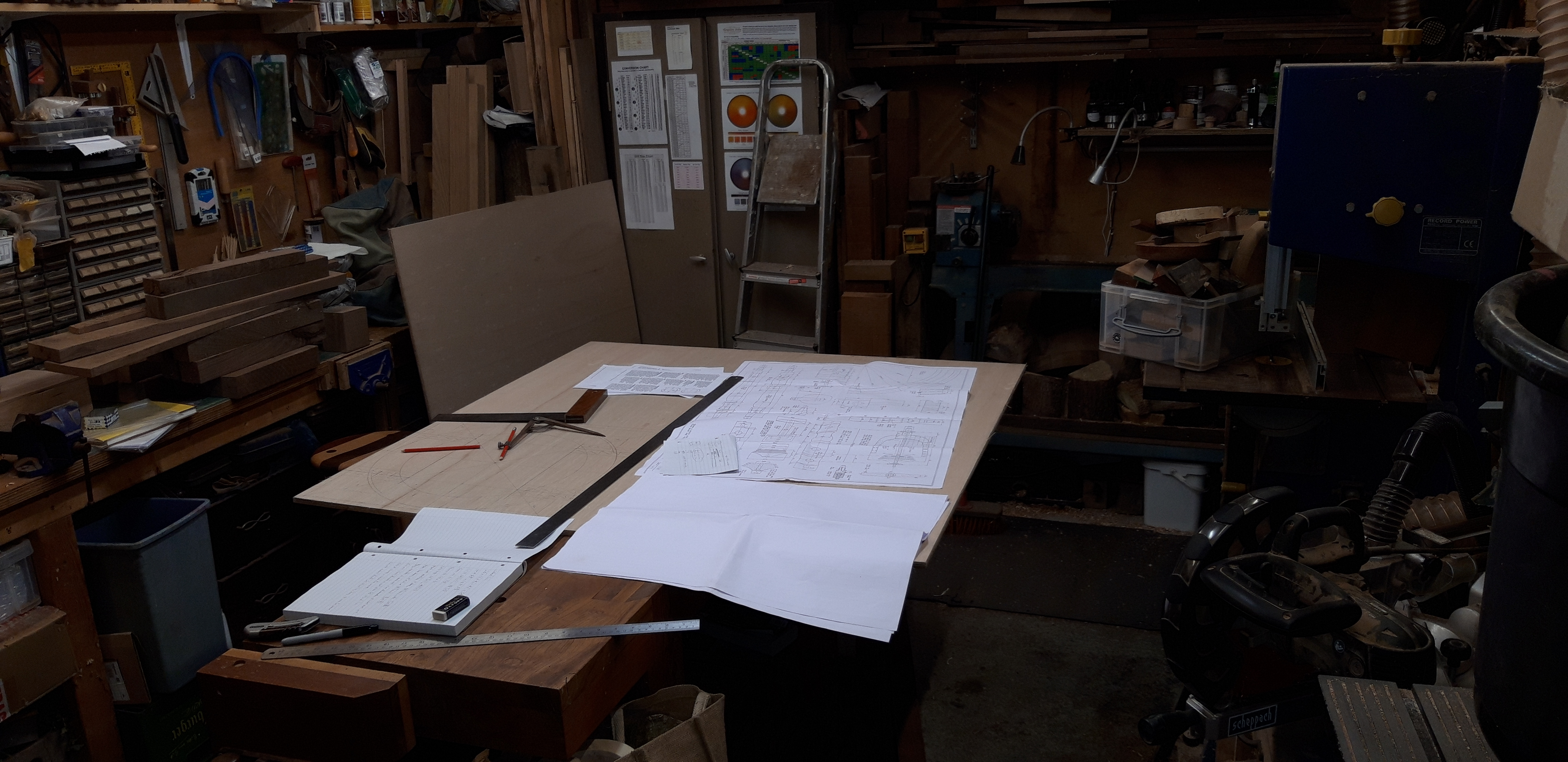
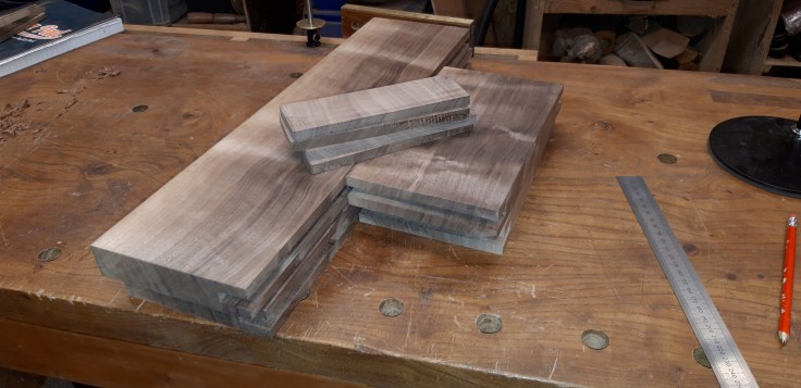
My wife managed to find me some plans online, from a chap called David Bryant at craftdesigns.co.uk. So I ordered them, sourced some of my favourite timber and set to work. Barring the wheel hub, the whole thing came from a single slab of walnut.

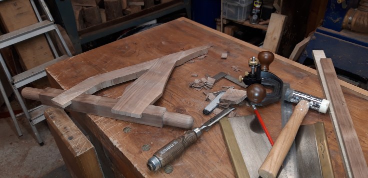
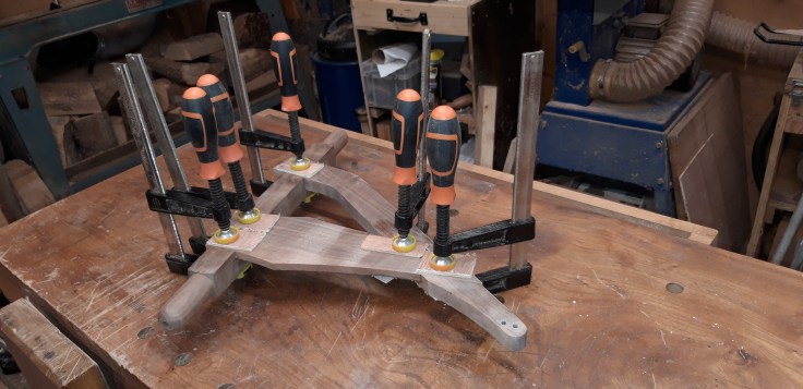
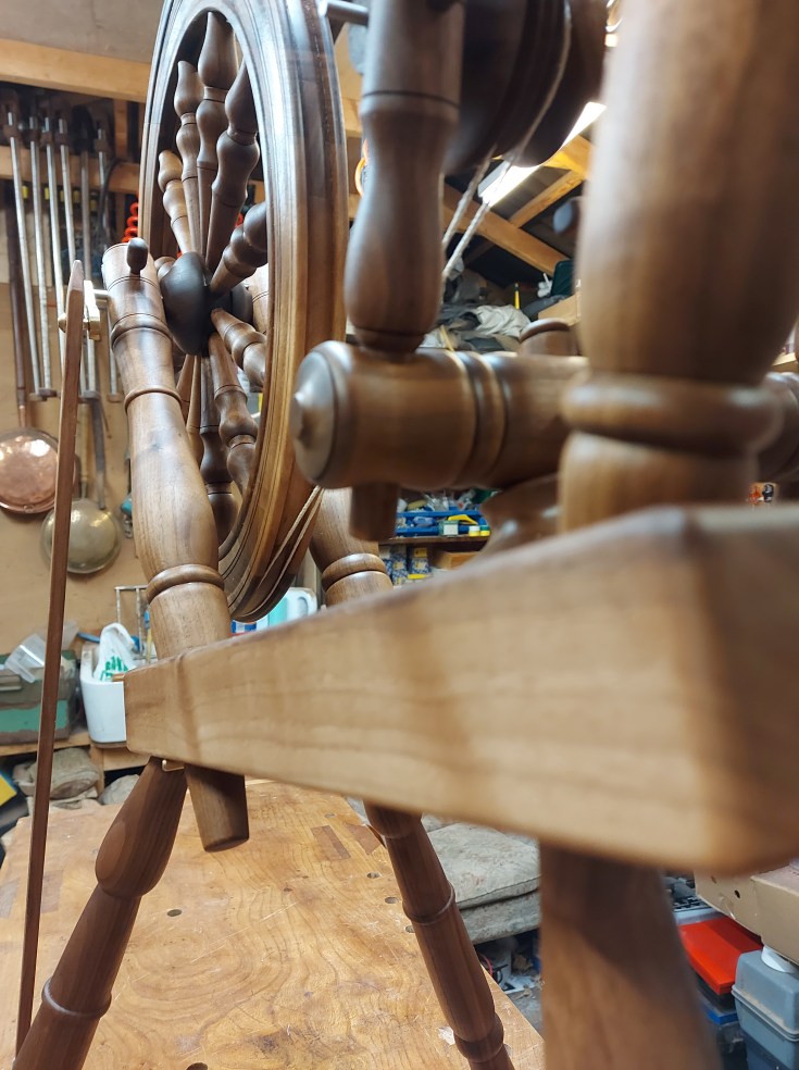
The Table
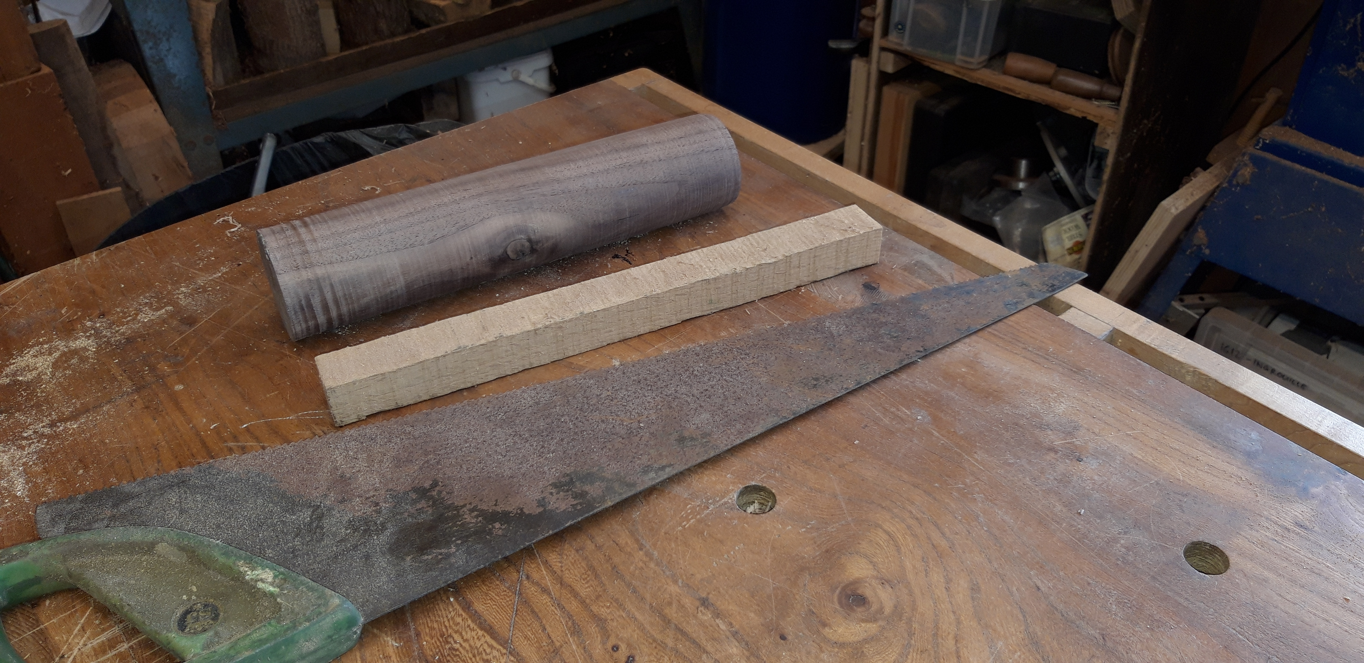
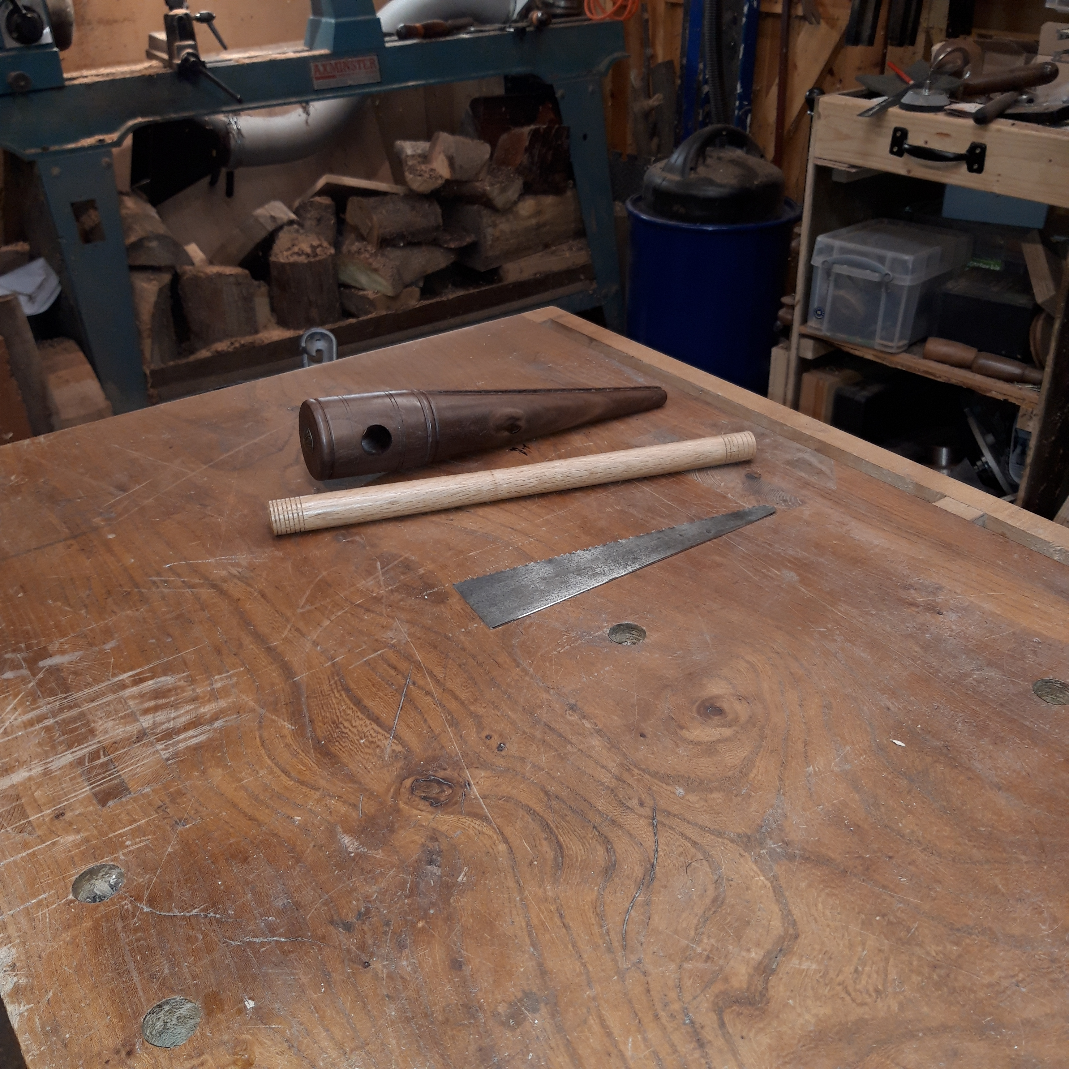
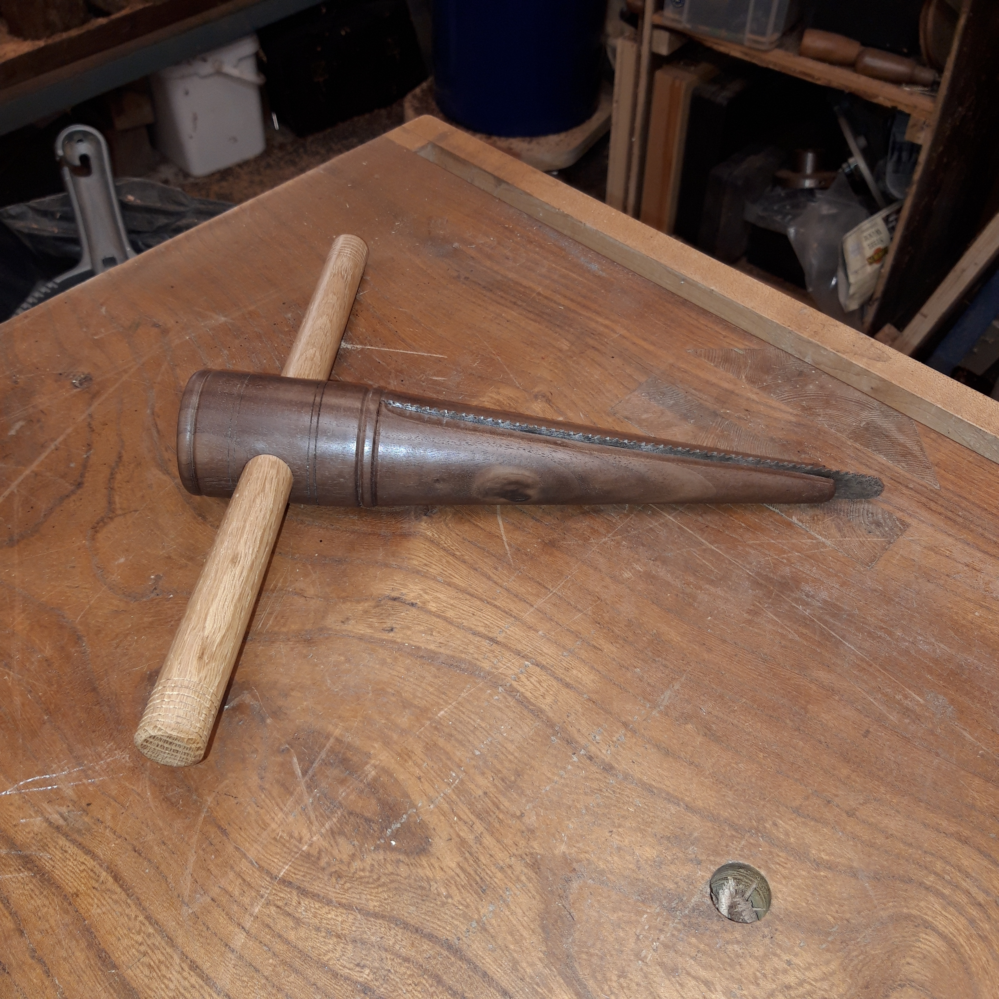
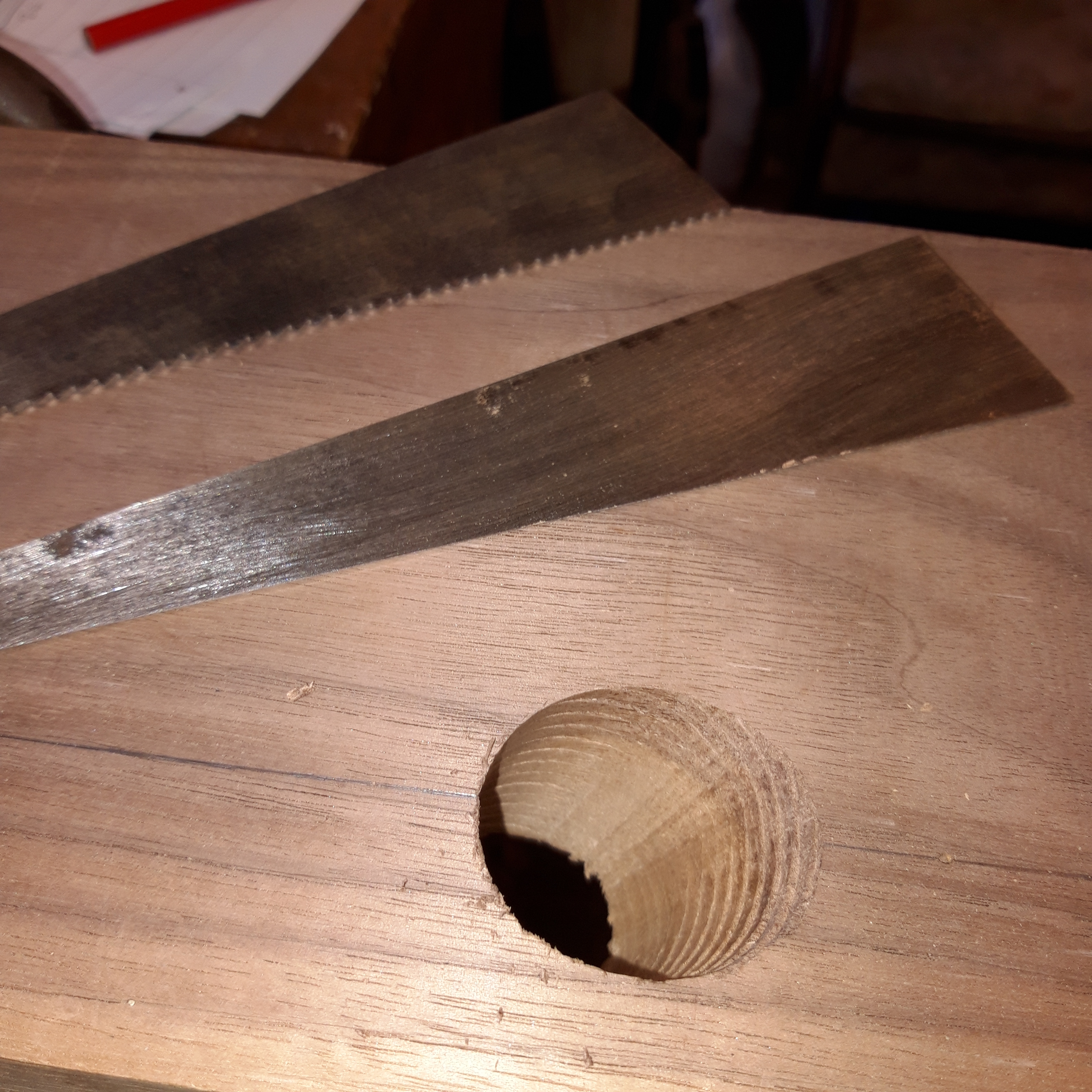
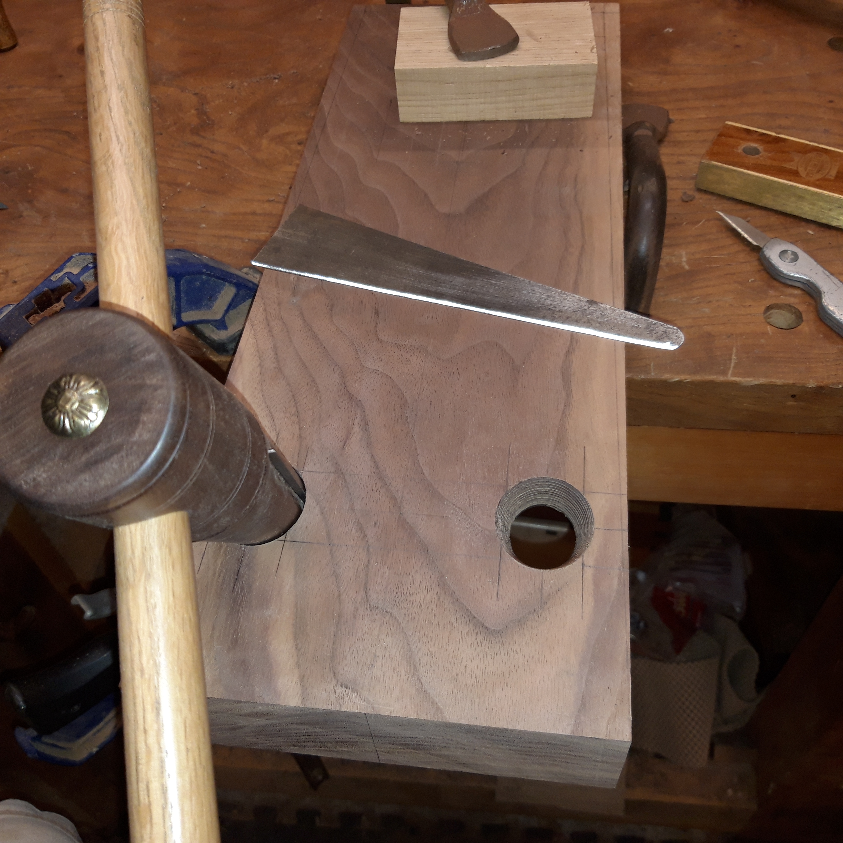
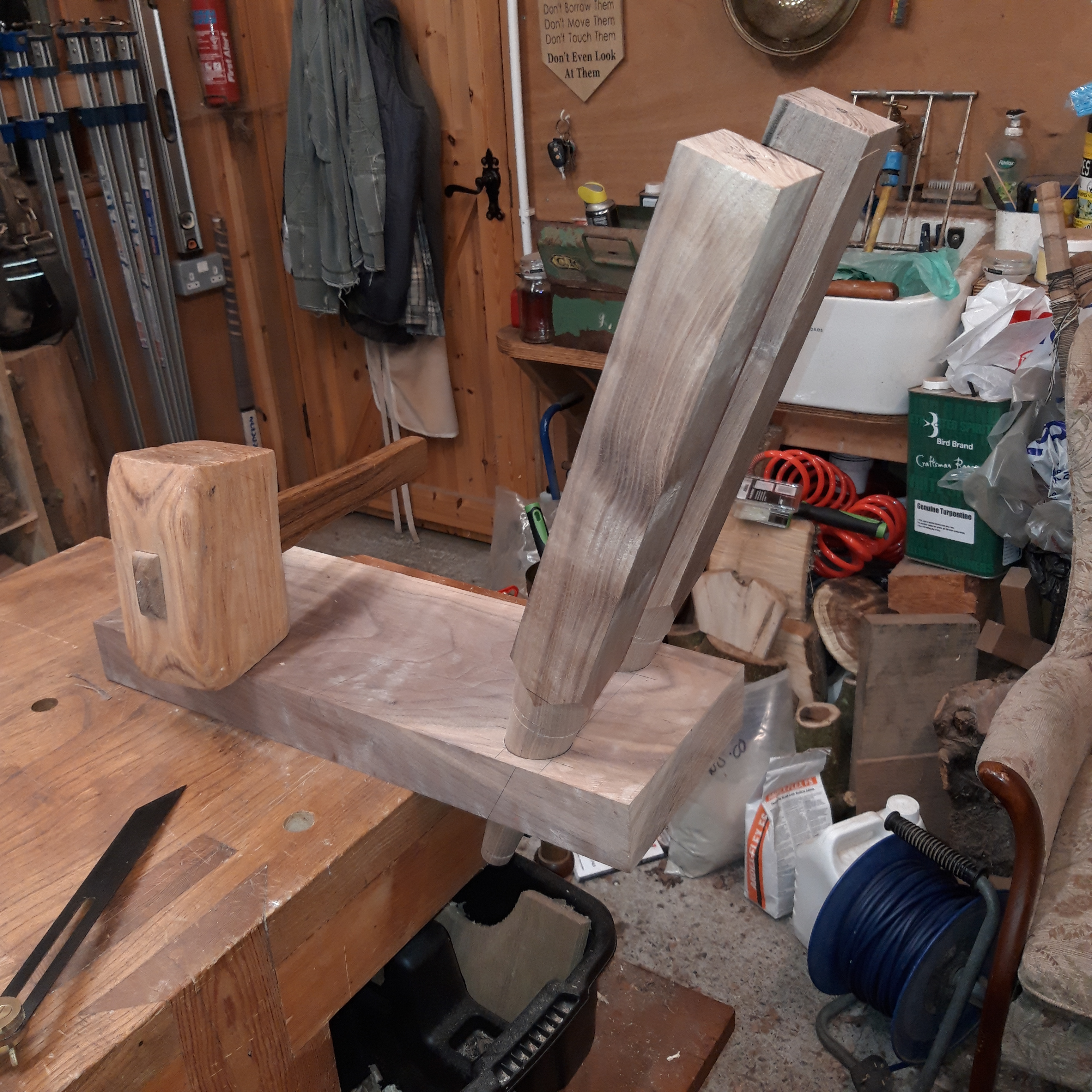
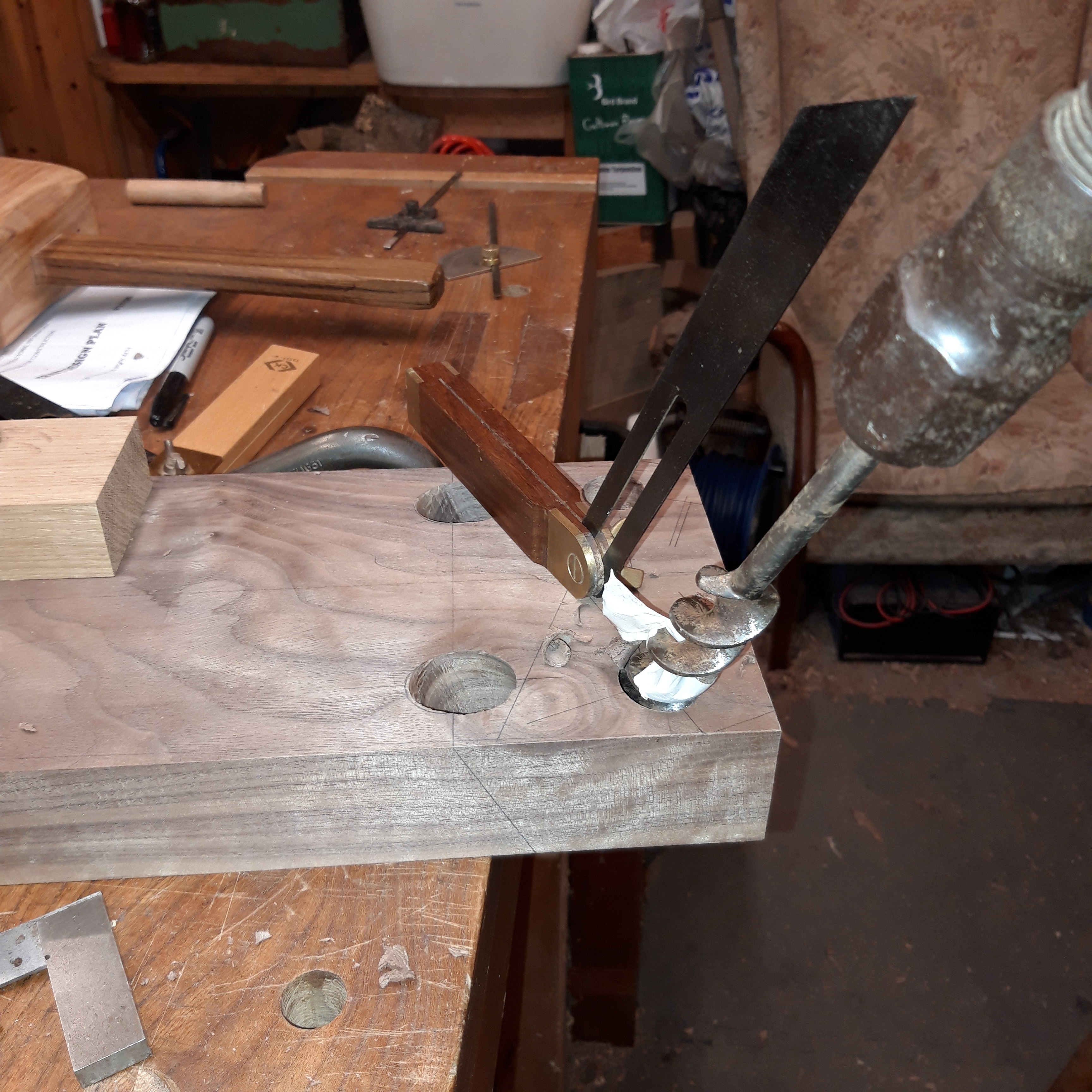
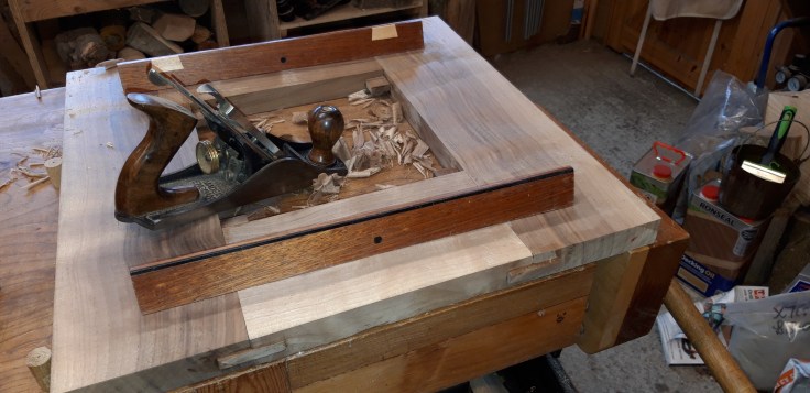
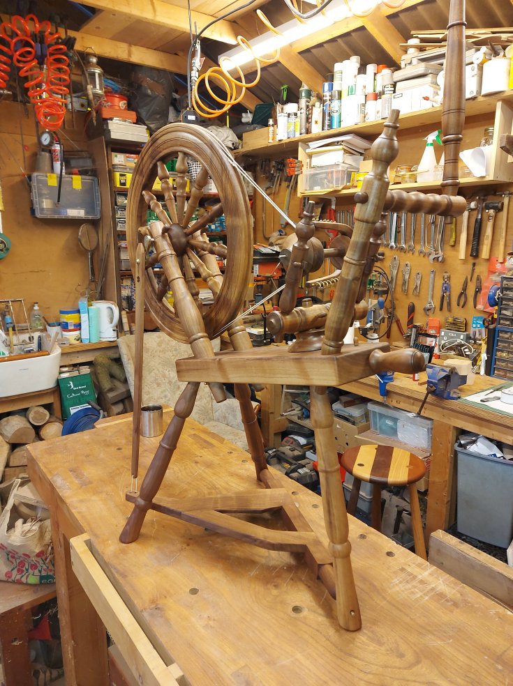
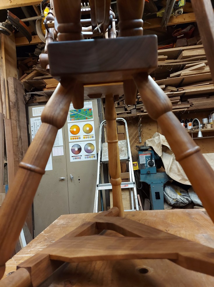
The table assembly is comprised of six main parts, a bed, two wheel supports and three legs. The wheel supports are held in place by a brass pin and are set into tapered holes, angled at about 60o to the bed. To accomplish this I had to build myself a tapered reamer and a couple of blades to taper the holes. The legs are fitted into angled holes under the bed and will eventually be glued in place.
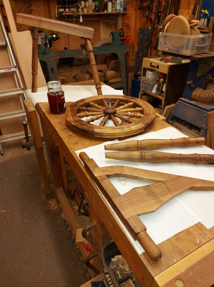
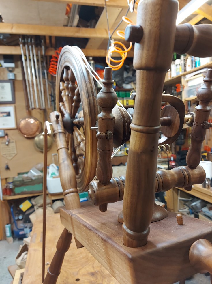
The Wheel
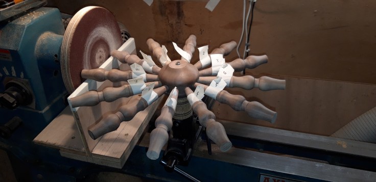
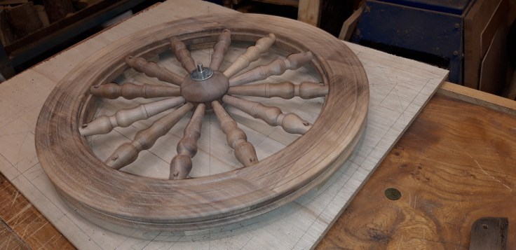
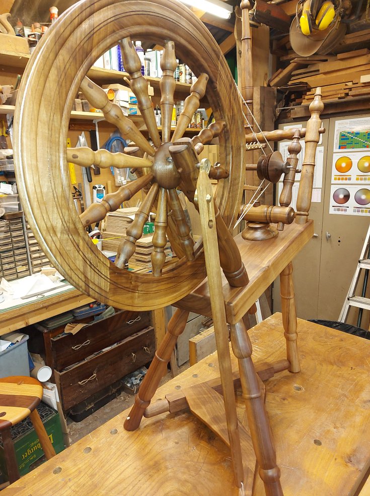
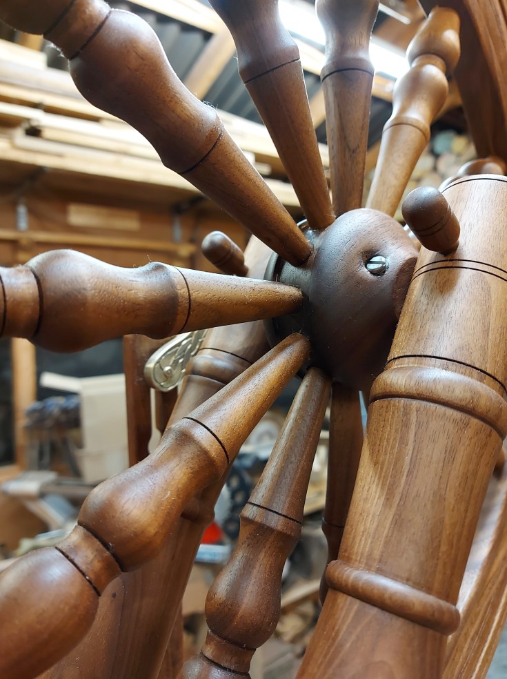
The wheel is made up of the hub, the rim and twelve spokes. Because the spokes needed to be identical, I made a plywood template to guide me as I was turning them. I turned the hub on a mandrel and, using an indexing system, I drilled the holes for the spokes. The spokes were then glued in place. I flushed the spoke ends on the lathe by mounting them on the tool rest and offering them up to a makeshift sanding disc in the headstock, revolving the assembly so that the spoke ends were exactly concentric to the hub. The assembly could then be let into a recess on one side of the rim before being glued and pegged in place.
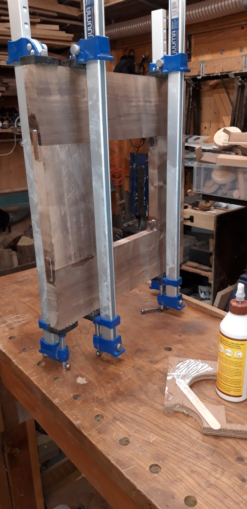
The rim was the biggest headache. Consisting of four main pieces, it was glued up as a square frame joined by four loose tenons. The the rough circular shape was cut out, leaving four waste areas on the outside by which it could be screwed to a large face plate, so that the inner face of the rim could be turned. I had to turn this outboard as it was too large to fit over the bed of my lathe.
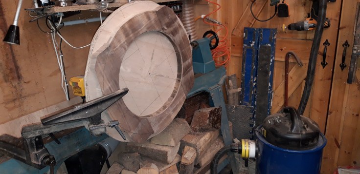
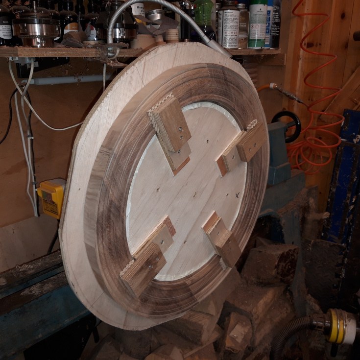

Once the final shape of the inner rim had been established on one side, it was flipped over to do the same on the other side. It was here that the recess for the spokes was established. Then, before removing it from the face plate, a disc of plywood, shaped to fit inside the rim exactly, was screwed in place. The rim could now be removed, the waste areas cut off and the rim affixed back onto the face plate. This was done by clamping it in place with scrap blocks screwed onto the plywood disc inside the rim. Then the outside face of the rim could be established, including the recess for the drive band.
The hub, spokes and rim were then glued up.
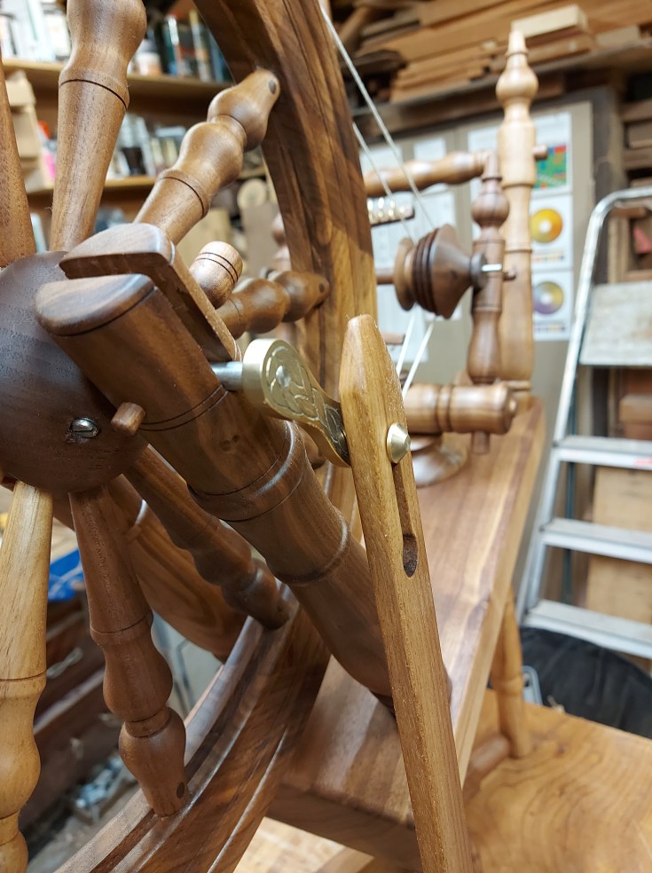
The Treadle and crank
The treadle is made up of three main parts, using simple half lap joinery. The assembly is joined to two of the legs with brass pivot pins and to the pitman rod which drives the crank.
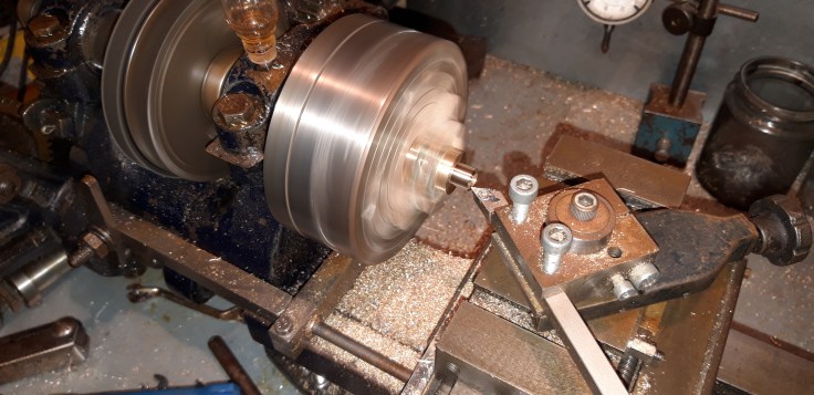
The crank is made from brass and I had a go at engraving it by hand. Not my forté. The crank is fitted to the main axle with a left hand thread, and to a crank pin which slots into the pitman rod.
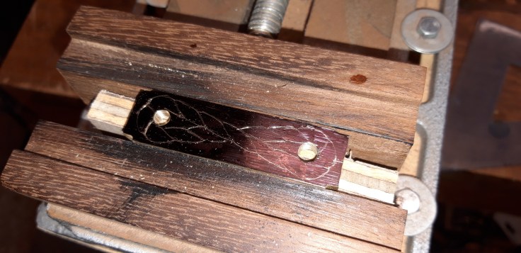
For a lot of the metal work I made use of my Dad’s engineering lathe. I had to have a crash course in metal turning as I haven’t done any since school.
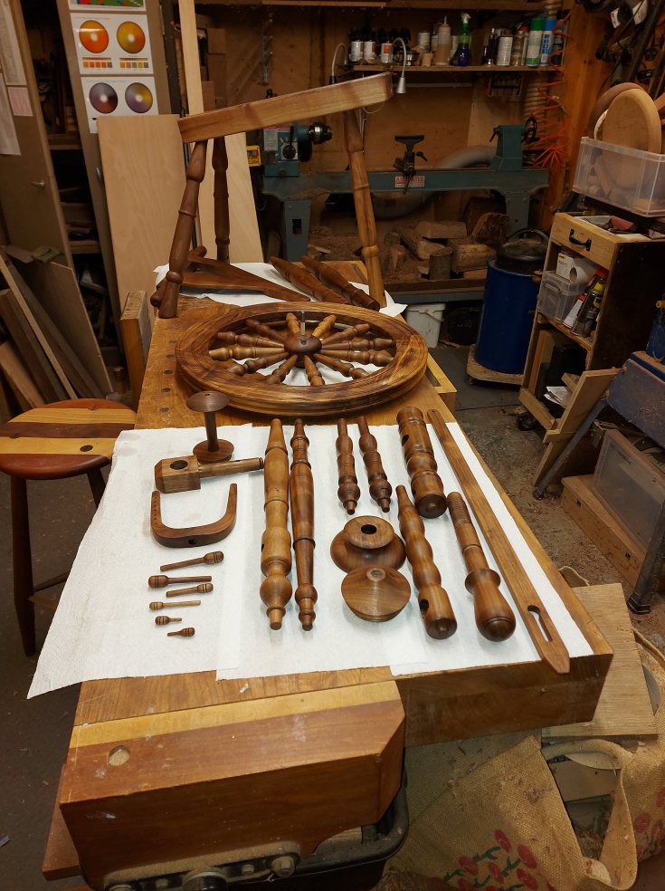
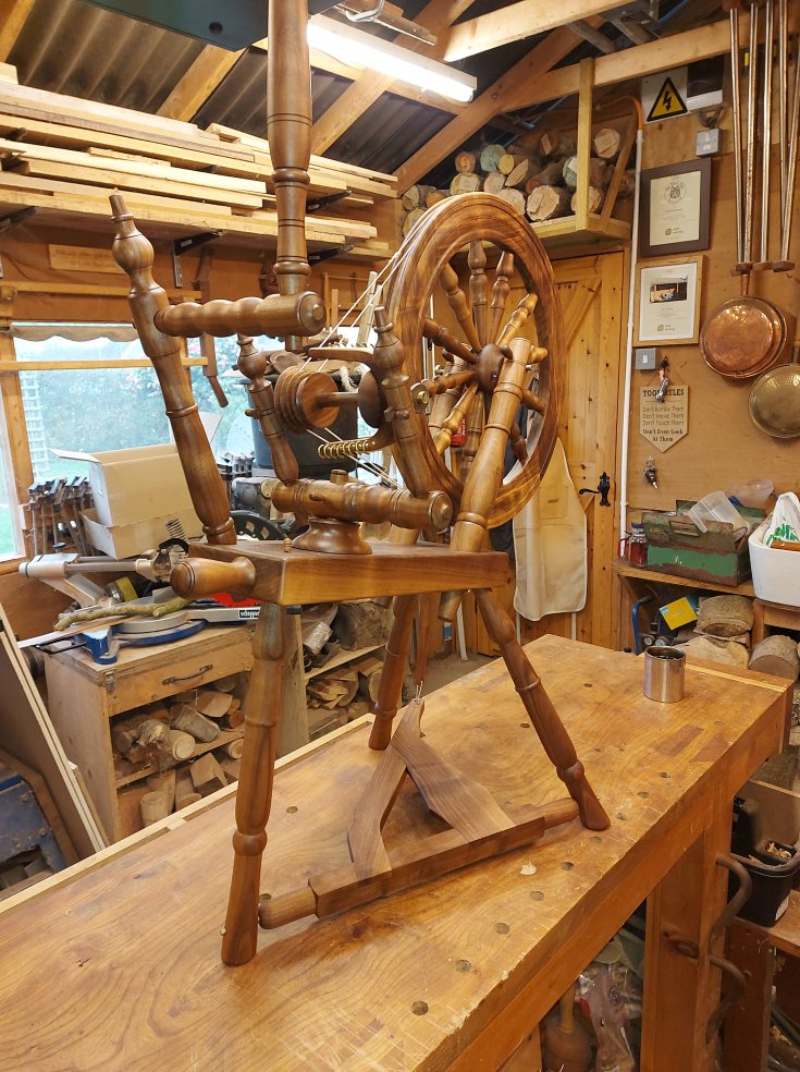
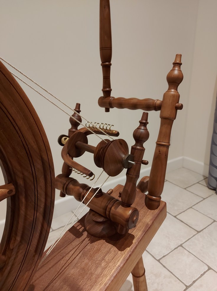
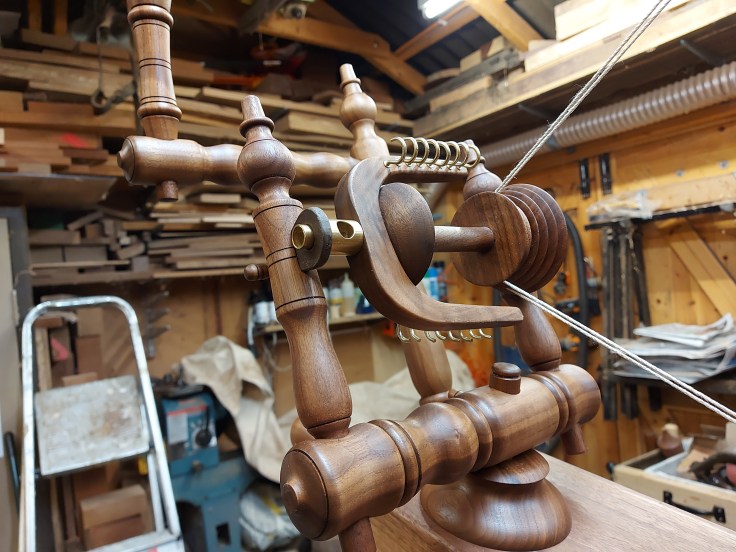
The flyer Assembly
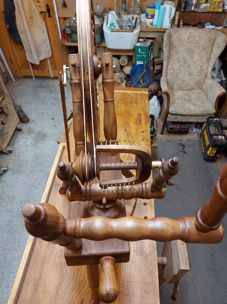
The flyer assembly is made up of several parts; the flyer, obviously, which serves to give the yarn its twist; the bobbin, which takes up the tension and spools the yarn when it is spun; the pulley whorl, which is driven by the drive band and in turn drives the flyer; the two maidens, which support the flyer and bobbin on leather bearings; the mother-of-all, which supports the maidens; and the tensioning assembly, which slides along the bed and is adjusted to tension the drive band.
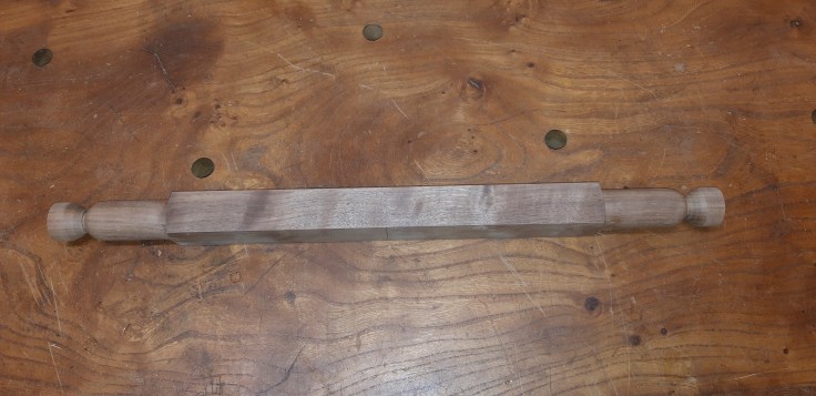
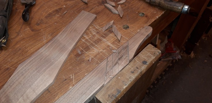
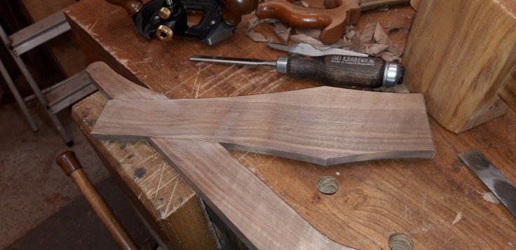
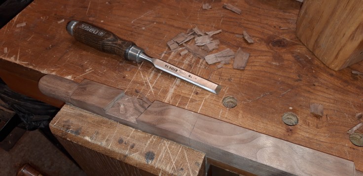
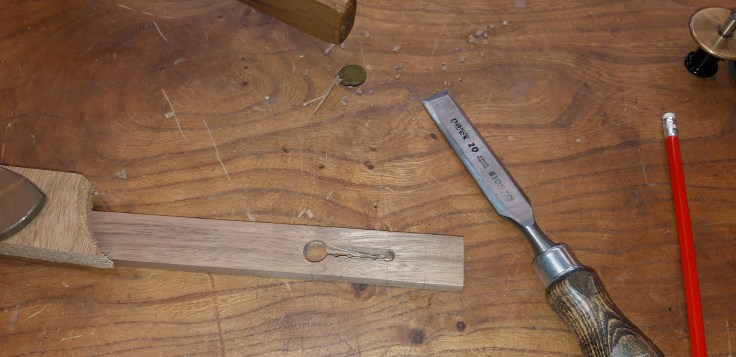
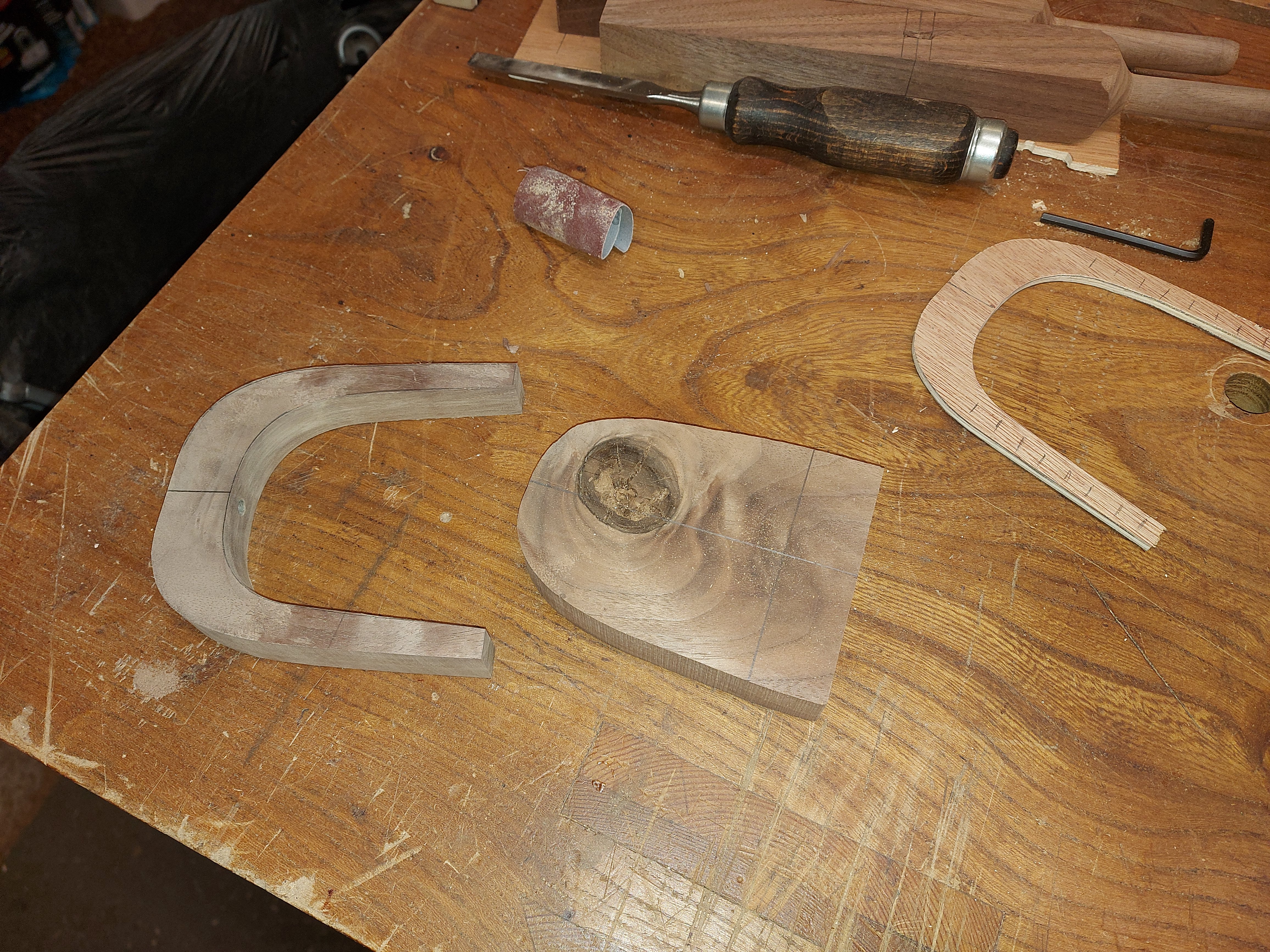
The flyer was made from a piece of timber with a large knot. I cut the knot out so that I could shape the flyer, making use of the fact that the grain wraps around the curve, avoiding any potential weakness.
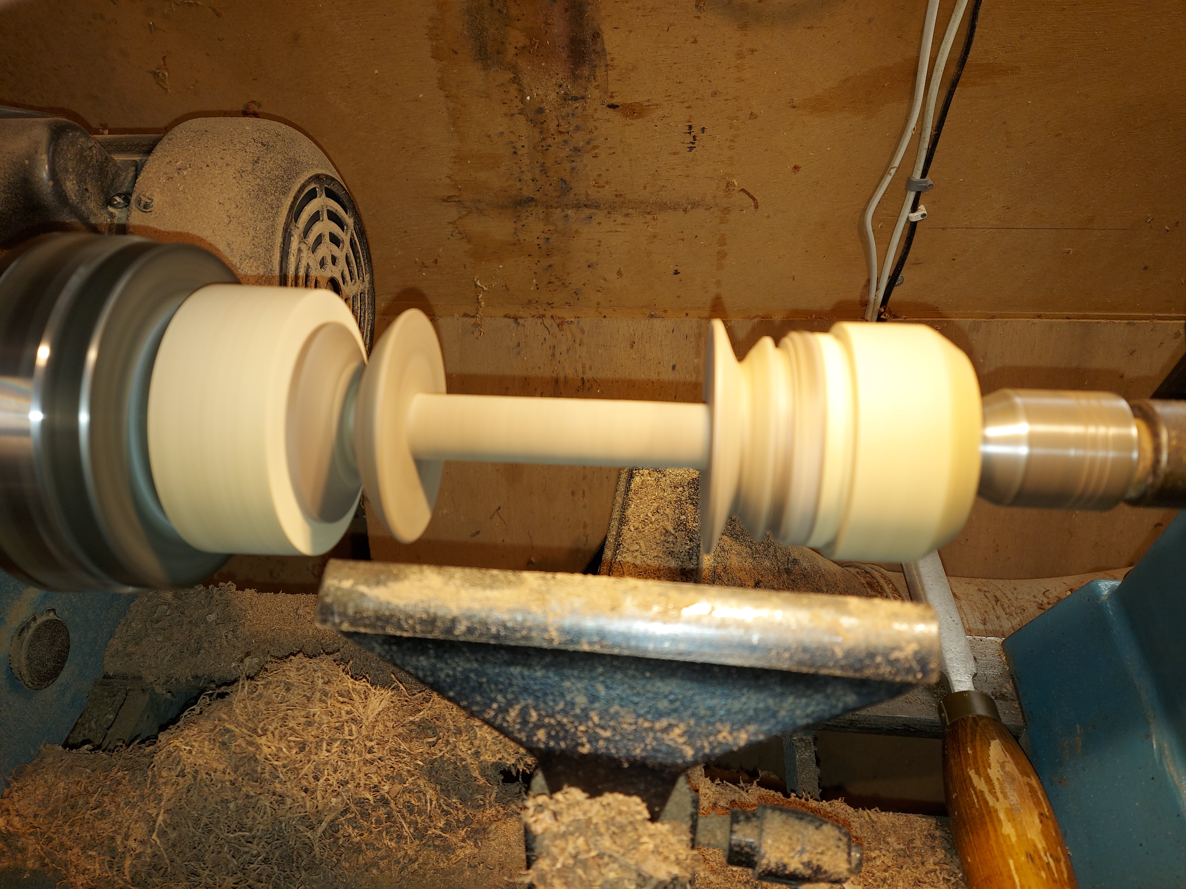
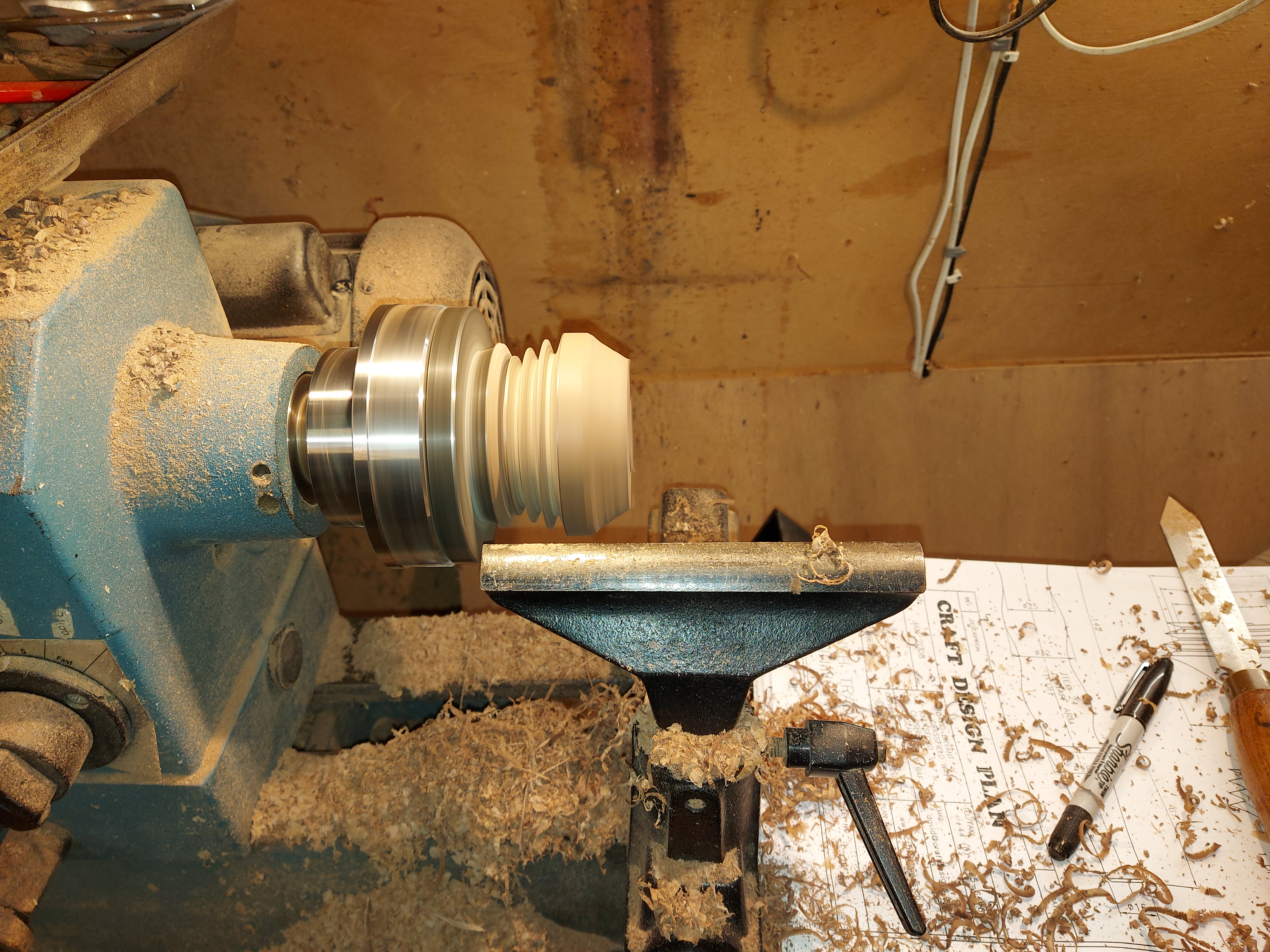
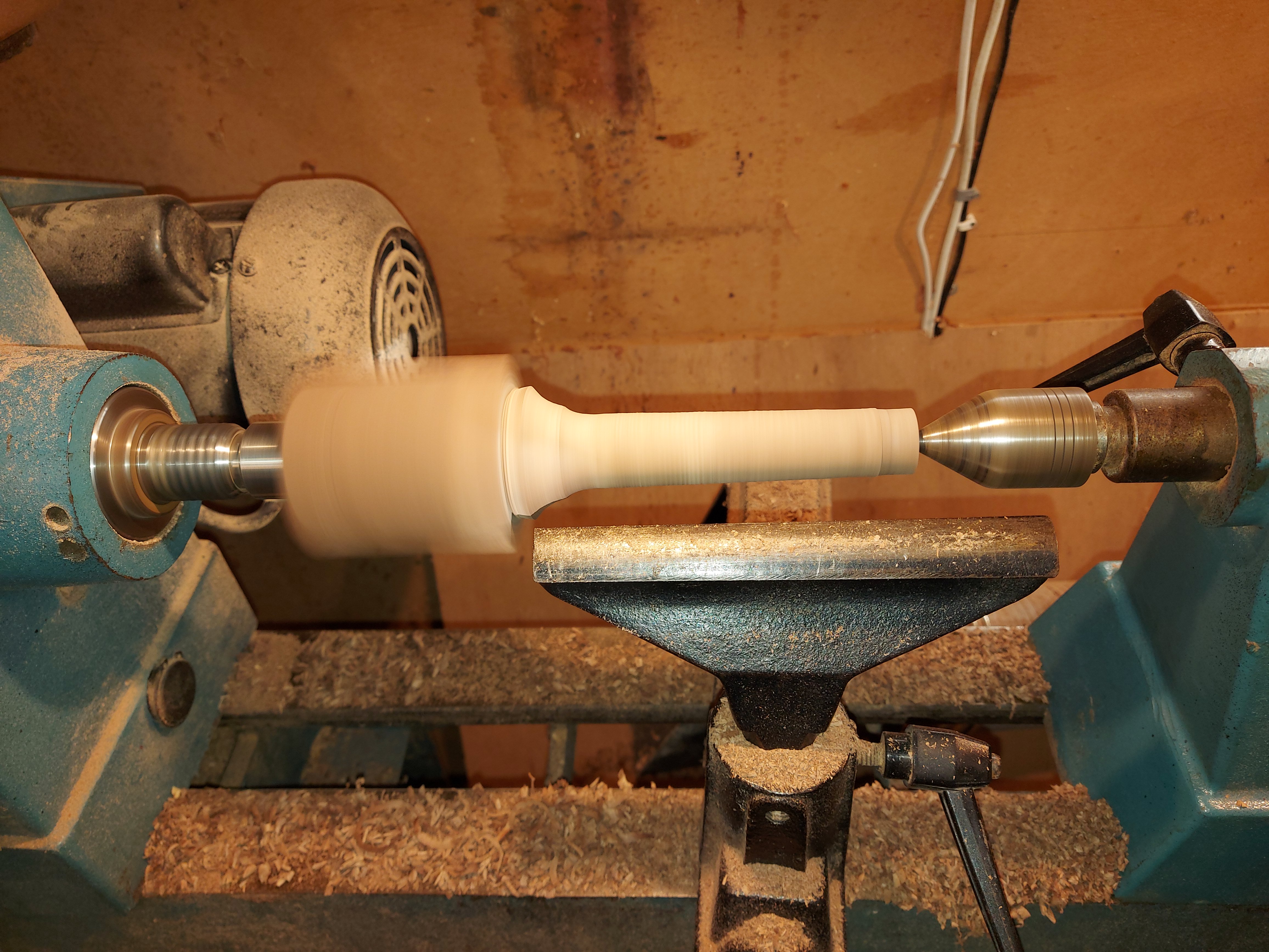
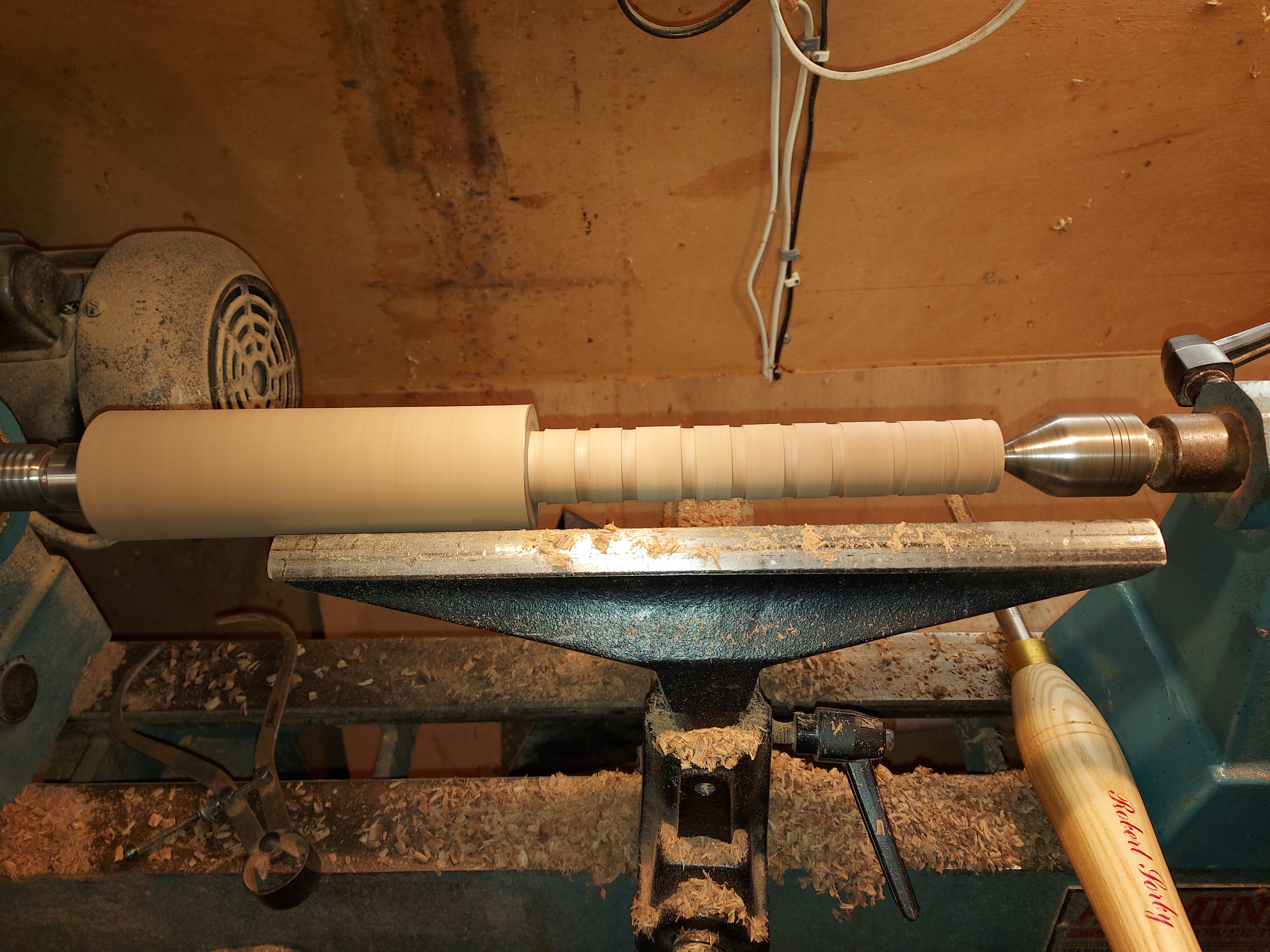
The bobbin is made from three parts, glued together and turned on a mandrel. The pulley whorl was turned in a chuck.
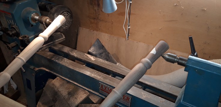
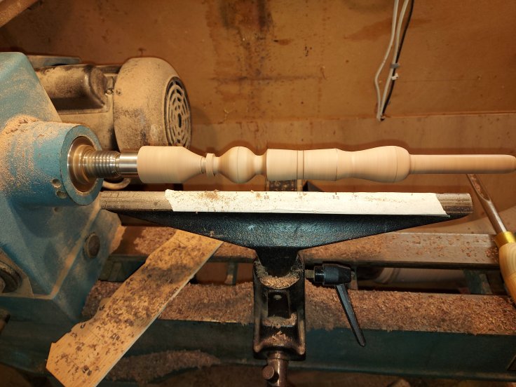
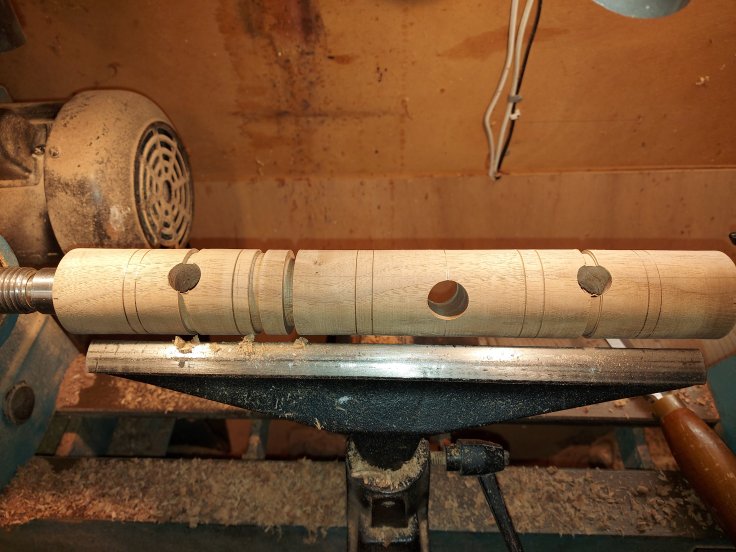
The three spindles were turned using templates, much like the spokes and I turned a dummy mother of all so that I could get the spacing of the holes exactly right before making the final one. The spacing of the holes is fairly critical as they determine how well the pulley lines up with the wheel.
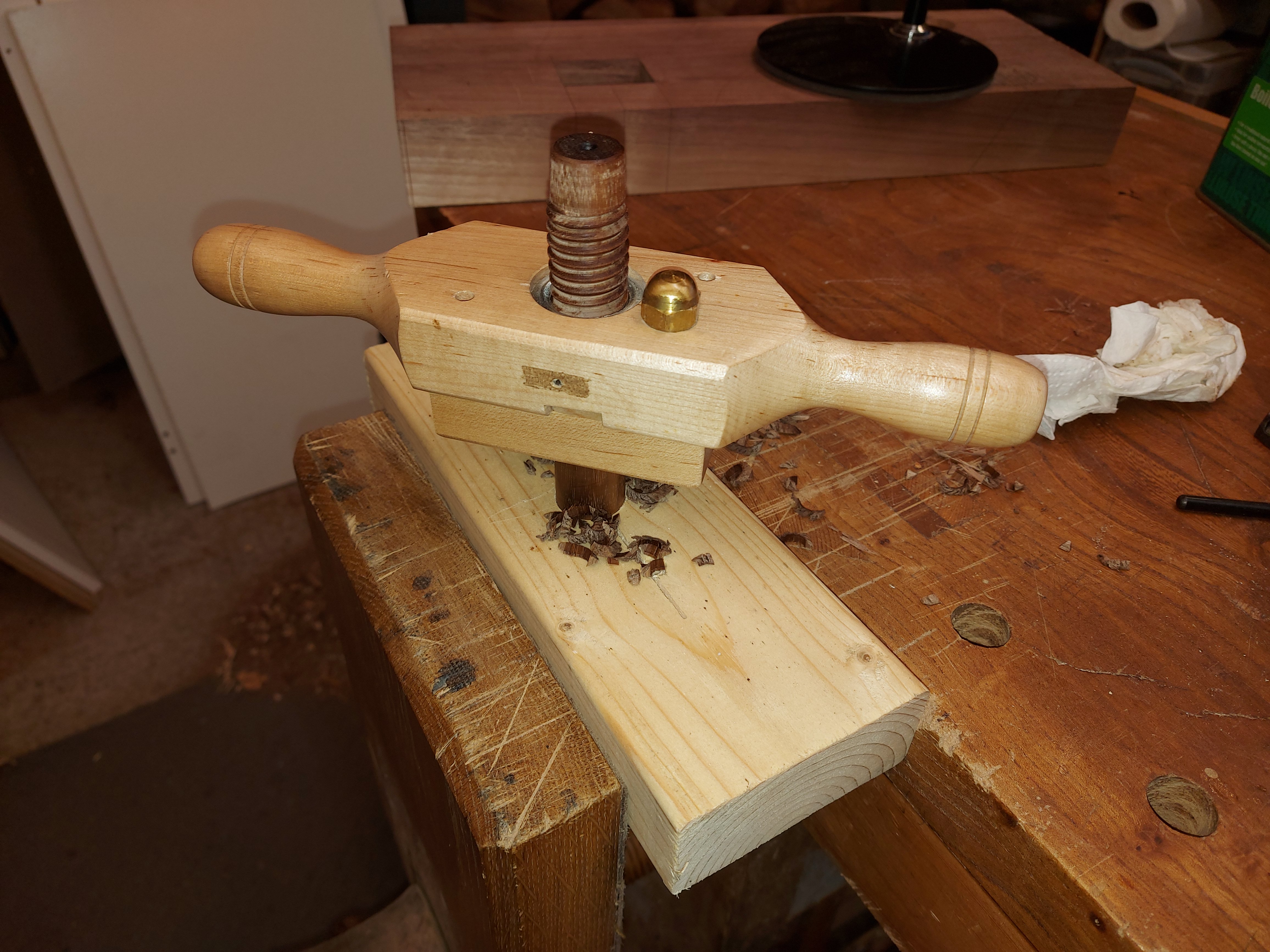
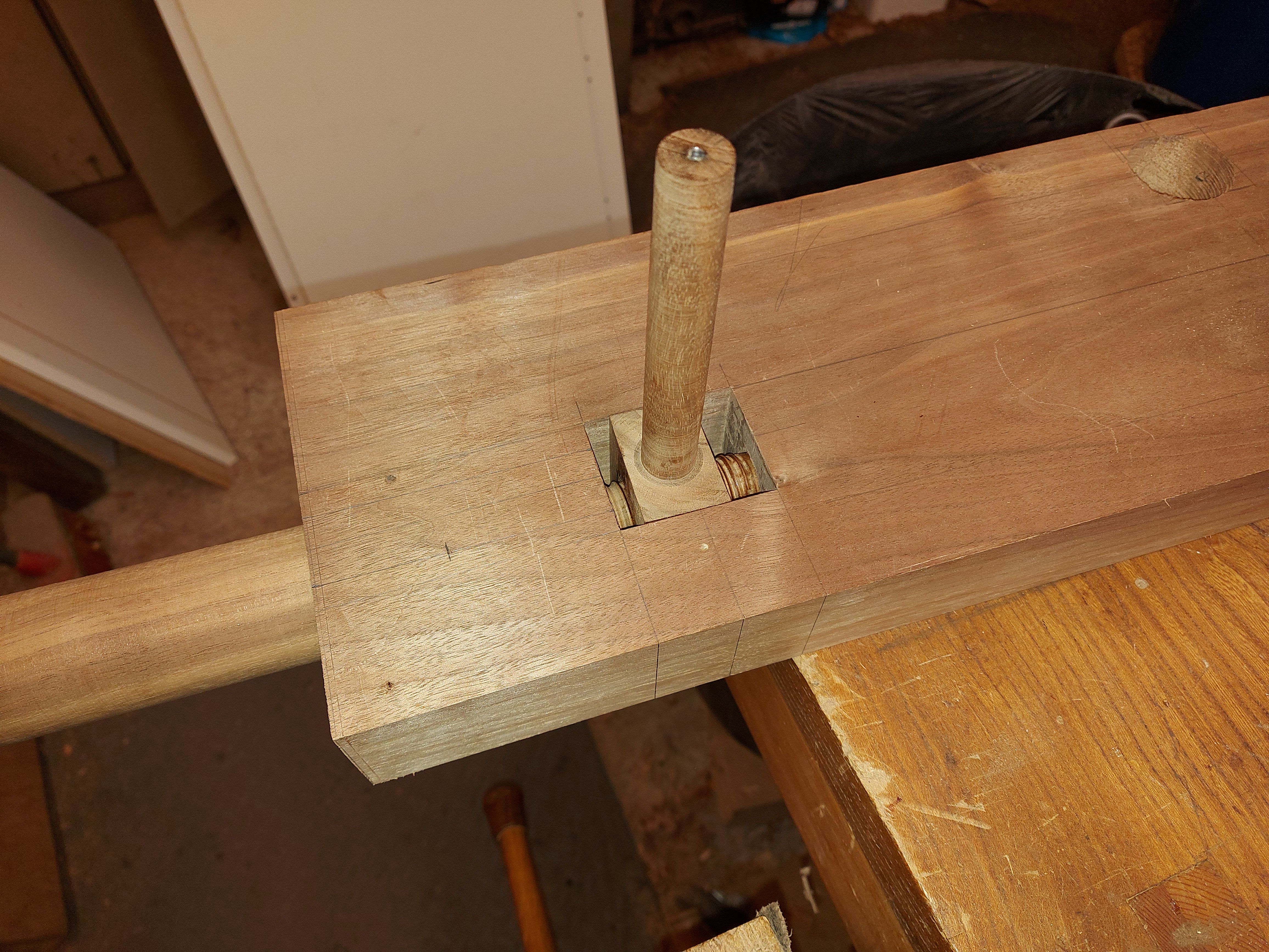
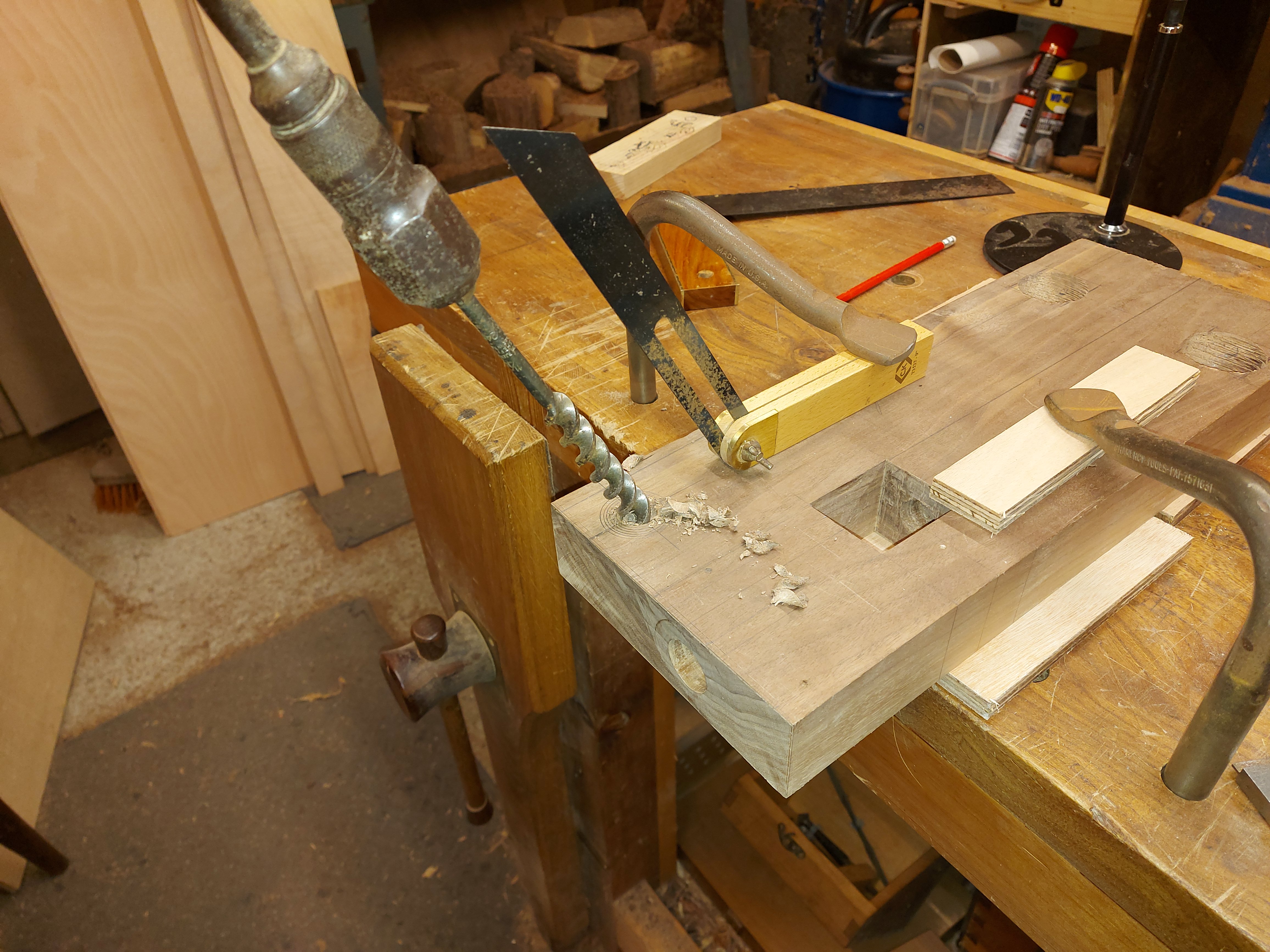
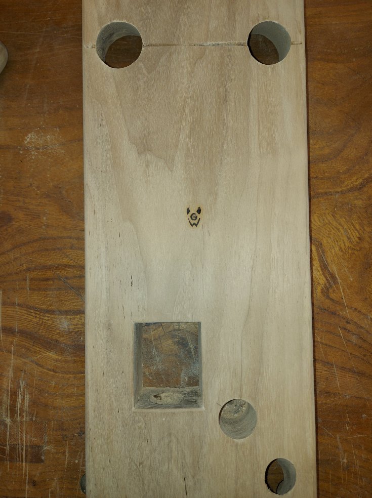
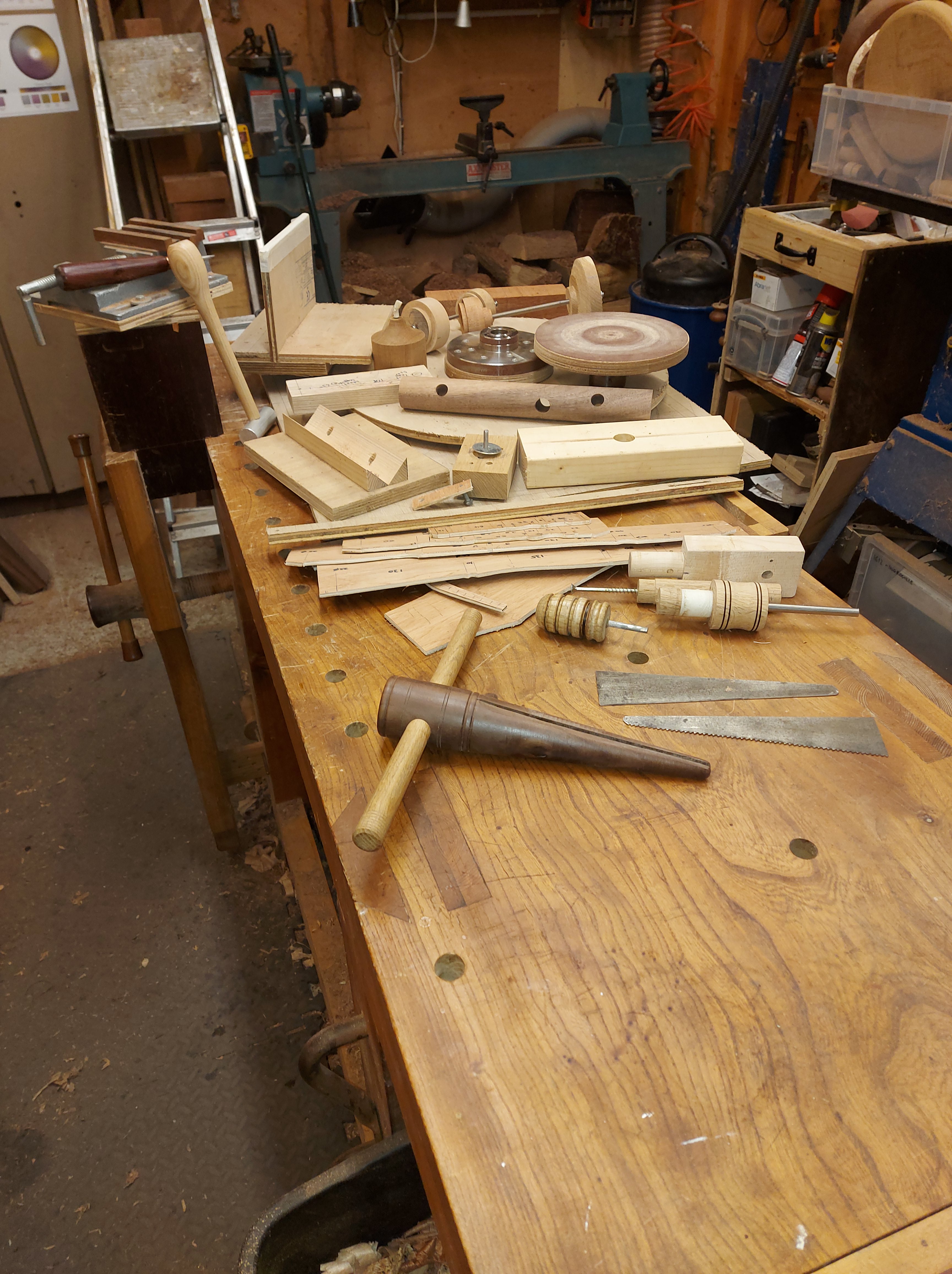
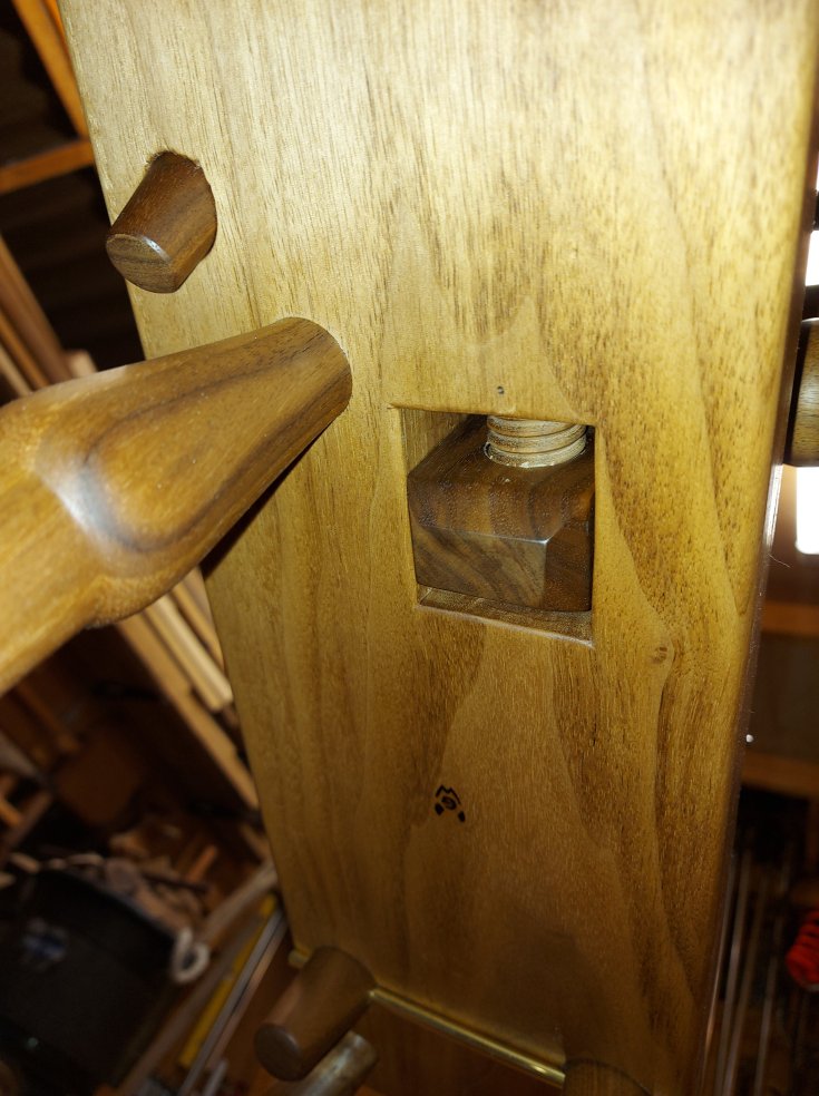
The tensioning system consists of a wooden screw and nut. The screw sits in a hole that goes through the end of the bed ( boring a 1″ hole through end grain with a brace and bit, such fun) and the nut sits in an adjacent square hole, and supports the flyer assembly.

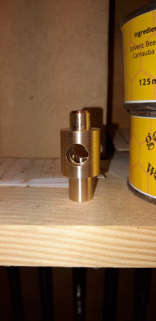
There is one other part that deserves a mention and that is the wonderfully named orifice. This is a brass component, turned on the engineering lathe, and was the most complicated metal component in the build. It has female thread at one end, which screws into the flyer axle, and an opening at the other which accepts the incoming yarn. It also has an intersecting hole at 900 to the opening which directs the yarn onto the flyer.
The Distaff
Finally there is the distaff, which is a three piece assembly that sits on the back of the bed, and serves to support the unspun yarn, keeping the spinners hands free. I understand that these days they are not much used, but I included it for the sake of authenticity.
The spindles were turned in the same way as the other spindles in this project, using plywood templates, and they are connected to the bed, and to each other, with more tapers.
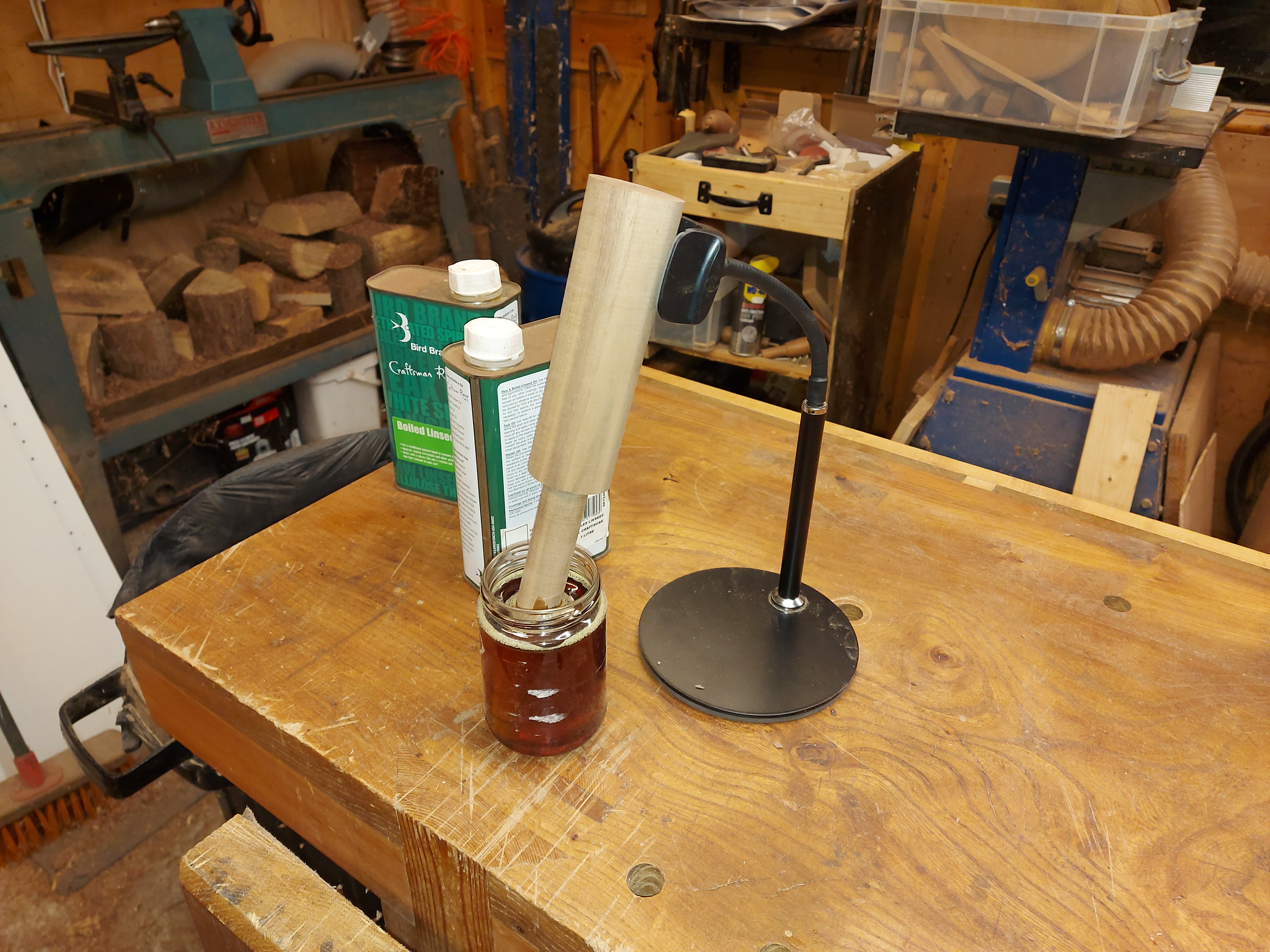
All of the wooden components were sanded to 400 grit and before finishing with a few coats my home-brew oil/varnish/turps blend. I also added my makers mark to the bottom of the bed.
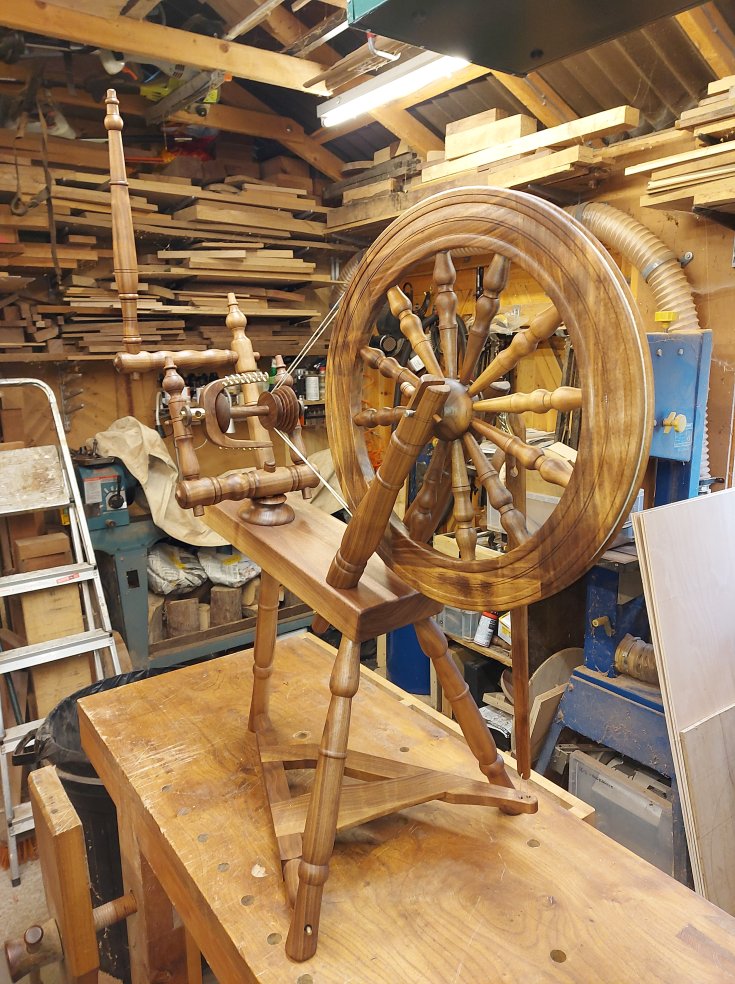
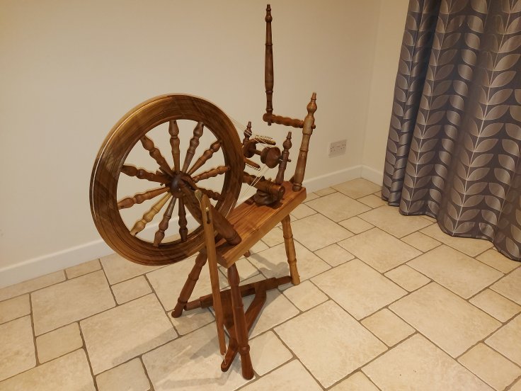
This might not have been my biggest project to date, but it was certainly the most complicated. I’ve never been so frustrated with my hobby before, but I’ve also never enjoyed it as much. I would definitely do this again. Having made one already, I’m sure the frustrations and the time involved would be reduced drastically. Not least because a lot of the hoops I’ve had to jump through are reusable.
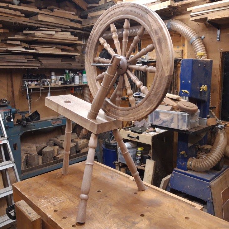
Anyway, here she is: A traditional spinning wheel, made from walnut, in the Saxony style, with a double drive system. I just need to learn how to use her.


Wow, I’d wondered where you had gone. I hadn’t received a notification from your site is a year or two. Nice work as always my friend. When I get the opportunity, I’ll try to make some more shop drawings for you. I’ve been tied up building my new house plan site. If you don’t mind my posting the url, it’s https://houseblueprint.net
LikeLiked by 1 person
Not a problem my friend. I’ve been too negligent of my blog this year. Hope to remedy that in the next.
LikeLike
Best build I’ve seen this year. Great job and thanks for sharing.
LikeLiked by 1 person
Wow. That is high praise indeed. Many thanks.
LikeLike
Sweet…
LikeLiked by 1 person
Hello, your beautiful spinning wheel is exactly the same as one I have. I presume made from the same plans. My problem is that the whorls and to some extent the bobbins have broken along the grain in places. It is still useable but I would love to replace them. Could you or could you recommend someone who could make a whorl and possibly a couple of bobbins for me?
I would be very grateful
Kind regards
Jayne
LikeLike